
5 oktober 2025
Members of our local amateur radio club recently started a project to experiment with an ESP6288 clone to create a WSPR transmitter. I stumbled upon this project and received the hardware design and accompanying sketch. The project is open source and is based on and built from various hardware and software designs. It’s still in the design and testing phase, so for me the right time to get involved and support the project.
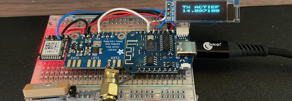
The hardware consists of a WM-386 (ESP6288 variant), a Si5351 clock generator, and an optional TinyGPS module. For RF, a 200 mW amplifier is designed with a BS170 and various inductors, capacitors and diodes to provide and switch low-pass filters (LPF) for the desired frequency.
My main focus was to redesign the sketch and make it possible to use the little transmitter both at home and in the field. At home, via the local network to retrieve the time from an NTP server, and in the field, via GPS to obtain time and location. In both cases, the unit must be configurable via the internal web server.
The main functions in the sketch are:
- loadConfig + saveConfig – The configuration is saved to an EEPROM-defined storage location.
- showOLED – Displays 2 or 3 lines of status information.
- htmlForm(s) – Configuration page for entering callsign, locator, power and band configuration.
- timeNTP – Obtain time from the NTP server.
- gpsRead – Read time and location from the GPS.
- calibrationLoop – Provides a calibration routine combined with a web interface.
- testLoop – Place the transmitter in a continuous loop for testing.
The main sketch does the following:
- Setup :
- Load the configuration.
- Define PIO, OLED, and initialize the Si5351.
- Connect GPS or WiFi.
- Check if optional GPS is enabled in the configuration:
- If yes and a GPS signal is received then load the time, adjust the locator and create a Wi-Fi AP for the web interface. The WiFi SSID (no password) and IP address are shown on the OLED.
- If not or no GPS signals received, connect to the local Wi-Fi network using the saved SSID and password.
- If there is no connection, create a Wi-Fi ConfigAP using a captive page to obtain the SSID credentials.
- If login to a local network is possible, connect and display the obtained NETWORK IP address on the OLED.
- Check if optional GPS is enabled in the configuration:
- Start the web server to provide:
- the configuration and calibration screens.
- mainLoop :
- Go into idle (no transmission) and show status on OLED.
- Based on band configuration start transmission – selecting LPF and frequency.
- use JTEncode to create the symbols for WSPR-2
- Show progress bar during transmission on the OLED.
- use the Adafruit SSD1306 libray as it can partial update the OLED (speed needed).
- Go into idle again.
- During idle time the web server is active!
The mainLoop is in essence a state machine that reads the time and uses a Frequency / LPF table to transmit the WSPR signal on the given Frequency using the correct Low Pass Filter in the correct timeslot. During this action a progress bar is visable on the OLED.
Above the various webpages provided by the sketch / unit. (click pictures to enlarge)
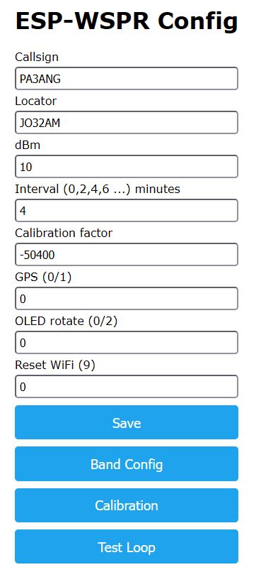
- The main page to enter the callsign, locator (if at home), output power and others.
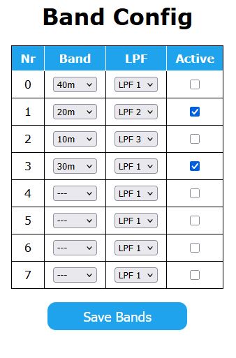
- Band Config will let you organise the frequencies and low pass filters (LPF) combinations. Based on the hardware variation 3 or 7 LPF are available.
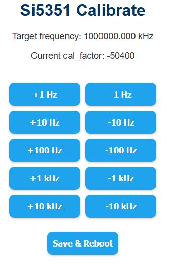
- Calibration page gives the opportunity to calibrate the Si5351 Clock Generator.
There are two specials in the main configuration screen.
1. If you wipe out the locator field and click SAVE the program will load the default settings.
2. Placing a 9 in the Reset WiFi field and SAVE will wipe out the SSID and place the unit in AP mode.
This was an interesting project for me, as I’d never worked with the ESP6288 (bare board) before, nor programmed Wi-Fi/web server routines. There’s a lot of information on GitHub, the internet, and forums about WSPR transmitters, but this compact and flexible system was new to me.
Thanks to PA3FBX and PD8GB for the original idea, and Jan, PA3FEX, for being my beta tester. We’re still working on improving the design and sketch. PCBs are designed for different variations: SMD/ThrougHole components and three or more LPFs to cover more bands.
Documentation and the ESP6288 sketch can be found @ github.com/pa3ang/ESP-WSPR
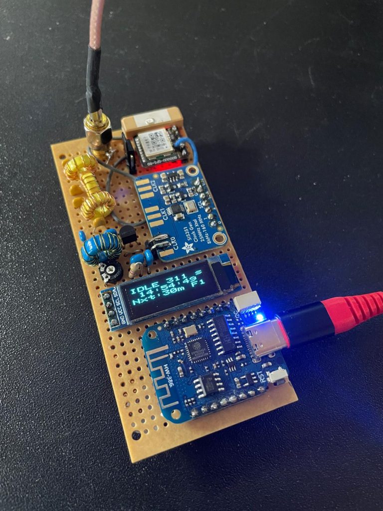
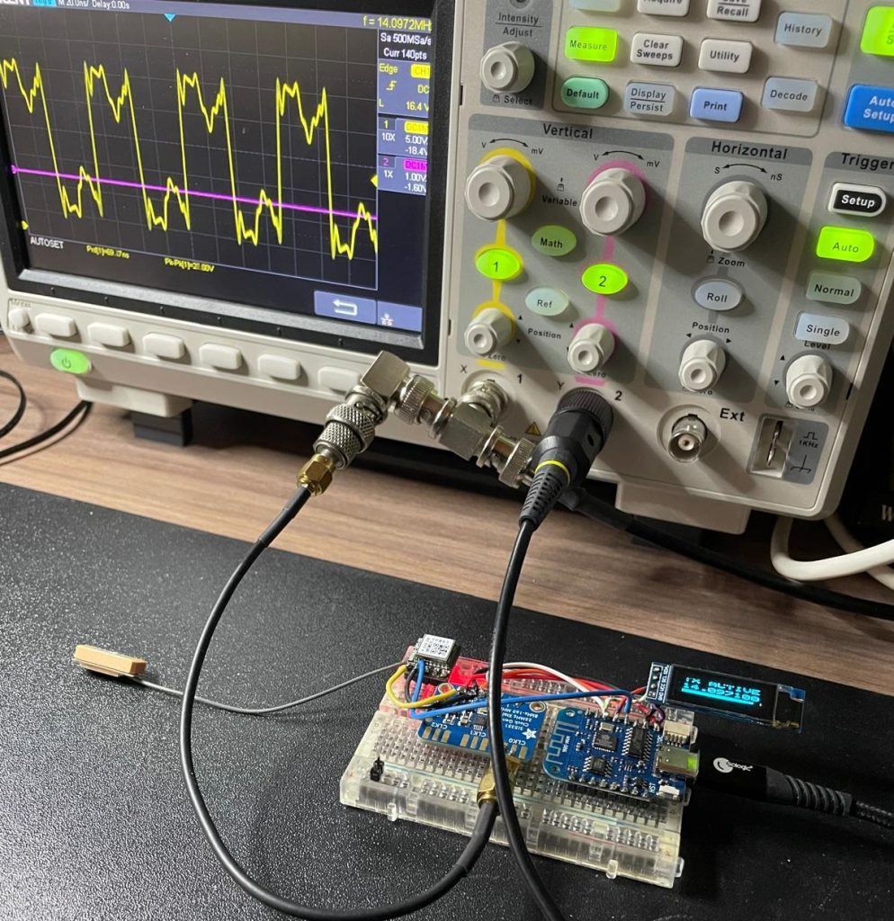
This is my final version on a prototyping board. Without enclosure, but suitable for software development and on-air testing with a decent power output of 200 mW (one BS170). The only available LPF filter on the board is sized for 20 meters, but also usable for 30 meters. The second harmonic of 20 meters is 60 dB and of 30 meters 40 dB down. On both bands, the third harmonic is suppressed by more than 80 dB.
Equipped with a TinyGPS, all variations are possible. PA3FEX tested the sketch with the 7-band version and it works fine.
In short, a fun project to work on and to combine several techniques.